Industrial ventilation systems – technical choices
What are the main physical quantities that operationally define a fan? How fans are chosen? Discover it with us!
In the previous article we saw some very important balance equations for the motion of fluids: the material balance and energy balance. In this article, in the light of developed awareness, we will examine more specifically the industrial fans and the quantities that characterize them.
We have seen that the law above is of fundamental importance in the analysis of fluid mechanics. In it, the following parameters appear:
- Geodetic contribution of the trio Bernoulli
- kinetic contribution of the trio Bernoulli
- pressure contribution of the trio Bernoulli
- contribution attributable to the pressure drop
The Bernoulli trinomial tends to preserve it in the different sections taken into account, considering the motion of an ideal fluid. Well, we live in a real world, where often the ideality approximation can not be applied. In the motion of a real fluid there is a further contribution in the equation: the dissipative effect, quantified by the load losses. This is related to viscous forces, which create phenomena of friction.
A new nomenclature
To carry out the analysis of the equipment of interest to us (the fans) are introduced a new nomenclature.
- The pressure contribution is called “static pressure“, as it corresponds to the pressure that the fluid exerts on the conduct or walls of the container in which it is contained. In continuing our discussion we will call this contribution Ps In the analysis of the fans this term is typically considered in a relative sense (with respect to atmospheric pressure). In other words, if the static pressure is lower than the atmospheric pressure, it will assume a negative value; if, however, is higher, it will take a positive value.
- The kinetic contribution is called “dynamic pressure“, and corresponds to the fraction of energy of the fluid related to the ordered motion of the molecules that make it up. We call this contribution pd.
- The sum of static pressure and dynamic pressure results in a quantity that we call “total pressure” and denoted by pt.
The unit of measurement used in S.I. for measuring the pressure is the Pascal (Pa). In the ventilation it is frequently used in another unit of measure, namely the millimeters of water column (mmH2O). For the conversion of units the following conversion factor can be used:
In the light of these considerations the initial equation can be written as follows:
If we consider the situation in which the geodetic variations are small (as often happens in the ventilation design) usually geodetic contributions are simplified. So, we get:
We note, therefore, that the effect of the pressure losses is to decrease the total pressure of the system. In particular, we ask ourselves: which contribution of the total pressure decrease? The One linked to the static pressure or the one linked to the dynamic pressure?
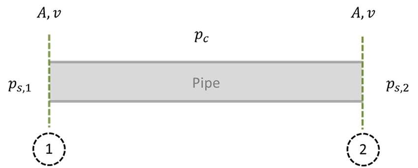
We had conducted a similar analysis in the previous article, and we have seen how the term which decreases due to the pressure loss is linked to the static pressure. This is caused by the fact that the velocity of the fluid (which appears in dynamic pressure) is governed by the material balance.
To ensure the conservation of the massive flow, the speed will vary only if there are the corresponding variations of density or of the passage section.

To ensure the conservation of the massive flow, the speed will vary only if there are the corresponding variations of density or of the passage section. Therefore, if we consider a constant cross-section pipe and a situation with scarce density variations, also the fluid velocity will be the same, and therefore also the dynamic pressure of the fluid will remain unchanged.
Let’s dive into the world of fans.
Analysis of the fans

Let us examine the structure together with a fan.
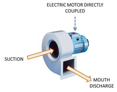
The pipes are connected to the fan through the suction and / or the discharge mouth. Via a specific internal blading, which thanks to an electric motor performs a certain number of revolutions per minute (rpm), the industrial fan is able to create:
- A low pressure area (Ps <0) in the vicinity of the suction mouth, in such a way as to convey the gaseous flow in its interior.
- An over-pressure (Ps> 0) in the vicinity of the discharge mouth, in such a way as to allow the flow to overcome the pressure losses of the output pipe.
So, as you can choose a suitably industrial fan? It is appropriate to clarify the benefits to be obtained.
Especially must be known:
- The volumetric flow rate (V ̇, often called Qv) that you want it to flow into the fan and their connecting pipes.
- The static pressure (Ps) to ensure that the fan must overcome the pressure losses and any geodetic variations of the flow. The pressure losses (localized or distributed) can be calculated on the basis of the constructional characteristics of the vacuum system, the flow and selection of the physical properties of the flow.
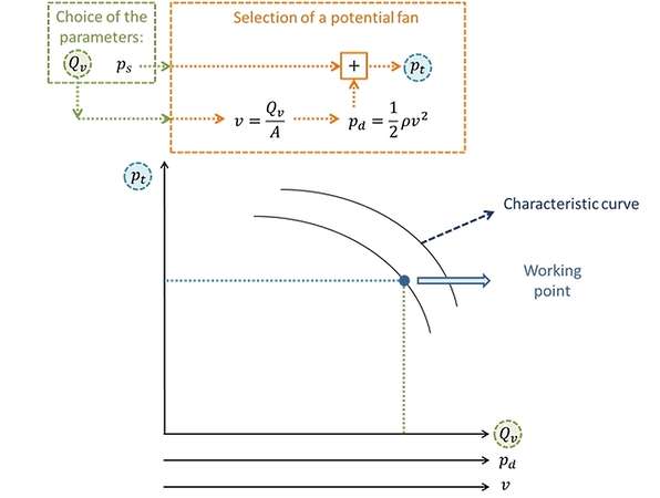
Based on these parameters (Qv and Ps) it can be made a first selection of potential fans, who can work in the required conditions. Each potential choice of the fan is characterized by its own characteristic curves, which describe their operation in different operating conditions. These characteristic curves are shown in a diagram, having:
- In the abscissa of the volumetric flow rate values (Qv), which is one of the parameters of choice. To each volumetric flow rate is associated with a certain dynamic pressure and a certain speed, typically reported in two axes to that underlying the abscissa axis. The values are calculated based on the properties of the fluid and constructive geometry of the fan (circulation areas). In the characteristic diagrams, for the calculation of the density (useful for evaluation of the dynamic pressure) it is typically considered to air at a temperature of 20°C and at ambient pressure.
- The ordinate shows the total pressure values (pt). Once you choose the value of the static pressure and once proceeds the value of the dynamic pressure (on the basis of Qv flow), it is possible to derive the total pressure as the sum of these values.In this way it is possible to determined the fan operating point within the diagram.

As can be seen in the image, inside of the graph appear a series of characteristic curves, each associated with a different number of revolutions of the fan. To the point of operation, using other parametric curves shown in the graph, you can associate:
- The sound power emitted at maximum efficiency (Lp, measured in dB)
- The system efficiency (η)
- The input power (in kW)
The fan chosen is optimal if in operating point ensures good performance, so if it is close to the maximum efficiency points, which are typically found in the central areas of the same curves.
If you were to deviate too much from the point of maximum efficiency it is good to choose a different type of fan. In particular, if you are too right than the maximum functionality points should choose a bigger fan of the same series. If you are rather too left it is convenient to choose a smaller fan.
Tecnosida® uses fans in the design of the suction systems. See our Case History and discover our creations!
See you soon with new items!